

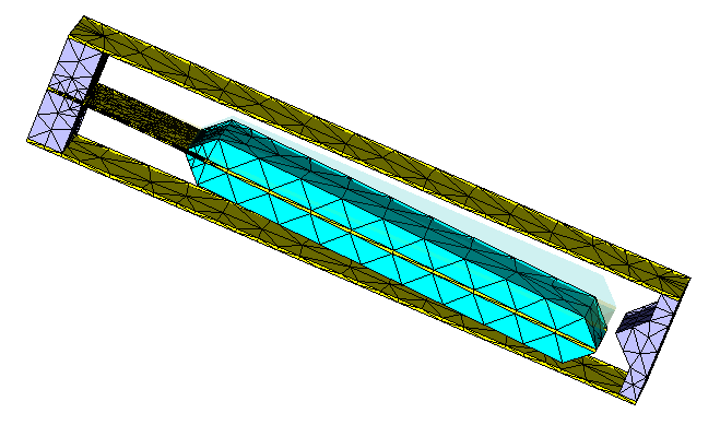
In this example a simple accelerometer is created. The model consists of two flat copper conductors with a third one between them, the latter fixed only at one end. If an acceleration occurs, the inertial forces push the third conductor towards one of the former two. If a voltage is applied to the outer conductors, the potential difference between one of them and the middle one changes according to the applied acceleration.
The model consists of three parallel copper plates with the size of 16 x 2 x 0.1 mm^3, the distance between them is 1.45 mm. Two thicker plates of steel are put on the middle conductor to make the system more sensitive to accelerations. The conductors are separated from each other by small plexiglas blocks.
Zero displacement boundaries are defined at the outer surfaces of plexiglas blocks. A traction boundary is assigned to the upper surface of the middle conductor, which roughly correspond to the acceleration of 17g.
The 2nd-order solver has been started, 6 steps of adaptive mesh refinement have been made. The accuracy has been set to 1e-6, which is sufficient for this computation.
The distribution of displacements, stresses and strains is available under "2D/3D Results" directory of the navigation tree. The deformation of the middle conductor can be visualized by choosing "Deformed Mesh" in sub-folder "Displacements".