|
|
|
| �� | |
| �� | |
| ��ҳ >> CST�̳� >> CST2013���߰���ϵͳ |
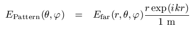
Farfield Source File FormatFile formatThe farfield source file may contain several linearly scaled farfield patterns (E_theta and E_phi) in spherical coordinates for phi = 0...360 degrees and theta = 0...180 degrees or several sets of electric and magnetic multipoles, depending on the file header. The frequency and optional power values must be specified for each frequency sample in the header as well.
Files can be created in the Farfield Plot �?General dialog from any farfield result, though any properly formatted data (e.g. measurements) may be used.
The specified file must contain the following information (See the examples below):
1. Version number, currently 3.0
2. Data type information. Supported formats are "Farfield" and "Multipoles".
3. Number of frequency samples.
4. Alignment: Position coordinates in meters, z-Axis and x-Axis of the antenna coordinate frame.
5. Frequency sample information. One entry for each sample is required:
The power information for the farfield excitation is expected in Watt (mean power). A new line for each value is expected. If this information is not available: a) If the Radiation Efficiency and the Total Efficiency are known the radiated power can be set to one and accepted power should be set to Radiation Efficiency = -1 and stimulated power should be set to Total Efficiency = -1. The power information will then be calculated automatically.
b) If no power information is available please set the values to -1. In this case the "Radiated power" will be calculated automatically and "Accepted power" and "Stimulated power" will be set to this value as well (i.e. the farfield source is assumed to be a perfect antenna).
The following data block depends on the specified format. "Farfield" requires:
6a. Total number of phi samples and total number of theta samples (both in one line separated by a blank or tab)
7a. Field pattern for all angles including phi =360 degrees
The "Multipoles" format requires: 6b. Total number of multipole entries 7b. Multipole data. Each line must contain Degree, Order, Re(a), Im(a), Re(b), Im(b). The electric multipole coefficients a are expected in V/m, the magnetic coefficients b in A/m. A special ordering of the multipoles is not required.
Several data blocks may be specified according to the number of frequency samples given in the header. Lines starting with // will be ignored.
See also
HFSS��Ƶ�̳� ADS��Ƶ�̳� CST��Ƶ�̳� Ansoft Designer ���Ľ̳� |
�� |
|
Copyright © 2006 - 2013 ��EDA��, All Rights Reserved ҵ����ϵ��mweda@163.com |
|