The second step of the construction is either to select a path curve. If a numerical value should be used for the extrusion of the profile one should press ESC to skip this step. If the profile should be extruded to a picked point, it is necessary to pick this point before activating the construction mode.
After the path selection was completed (either by selection or pressing ESC) a dialog box opens where all other settings can be defined.
In total there are six different ways to define a coil segment:
|
|
Profile: selected curve |
Profile: picked face |
|
Path: |
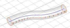
1. Activate the creation tool 2. Select the closed profile curve 3. Select the open path curve
Coil segment created from a profile curve (blue) and a path curve (red)
|
1. Pick a planar profile face 2. Activate the creation tool 3. Select the closed profile curve
Coil segment created from a picked face (red dots) and a path curve (blue) |
|
Path: (needs to be picked before tool activation) |
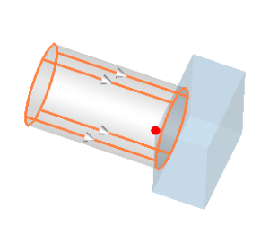
1. Pick a point 2. Activate the creation tool 3. Select the closed profile curve 4. Press ESC to open the dialog box
Coil segment created from a profile curve and a picked point |
1. or 2. Pick a planar profile face 1. or 2. Pick a point 3. Activate the creation tool 4. Press ESC to open the dialog box
Coil segment created from a picked face (red dots) and a picked point (red)
|
|
Path: |
1. Activate the creation tool 2. Select the closed profile curve 3. Press ESC to open the dialog box
Coil segment created from a selected profile curve and a numerical value for the extrusion height |
1. Pick a planar profile face 2. Activate the creation tool 3. Press ESC to open the dialog box
Coil segment created from picked face (red dots) and a numerical value for the extrusion height
|
Cancel interactive mode
You may cancel this interactive mode at any time by pressing the ESC key. This will open the dialog box where one may cancel the creation by pressing the Cancel button.
See also
Curve Creation, Pick Face Mode, Pick Point Mode, Define Coil Segment