

This type of block implements a voltage-controlled switch. Depending on the voltage between port 3 and port 4, the switch contact between ports 1 and 2 is either closed or open.
The block is characterized by the properties listed below. To modify the values use the Block Properties – Parameters dialog box.
|
Initial Condition |
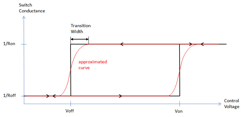
Since the switch may exhibit a hysteresis, the on/off state may not be unique at simulation start. This parameter sets the initial condition and thereby choses the branch of the hysteresis curve. |
|
On Resistance |
Resistance between ports 1 and 2 in "On" state. |
|
Off Resistance |
Resistance between ports 1 and 2 in "Off" state. |
|
On Controlling Voltage |
The voltage that switches the switch from "Off" to "On". |
|
Off Controlling Voltage |
The voltage that switches the switch from "On" to "Off". The switch exhibits a hysteresis if this voltage is different from the On Voltage. |
|
Parallel Capacitance |
The value of a capacitance connected in parallel to the switch contact. |
|
Transition Width |
Width of the transition region in hysteresis curve. A value of 0 corresponds to an idealized, abrupt hysteresis curve. |
Since an ideal switch is a highly nonlinear device, it may lead to instabilities in transient simulations. These can usually be fixed by setting the Parallel Capacitance parameter to a small nonzero value, and/or limiting the ratio of Off Resistance to On Resistance to a value less than 1012.
Note that the hysteresis curve of the voltage-controlled switch is approximated by a continuous curve which is shown qualitatively in the figure below. .This might avoid convergence problems during transient simulation, when the switch is neither in a clear ON state nor in a clear OFF state. The smoothness of the hysteresis curve is controlled by the parameter Transition Width.
See also