

This type of block implements an arbitrarily-angled bend in a microstrip line.
The block is characterized by the properties listed below. To modify the values, use the Block Properties – Parameters dialog box. The common substrate properties are defined by a Microstrip Reference Block.
|
Width |
Width of the trace |
|
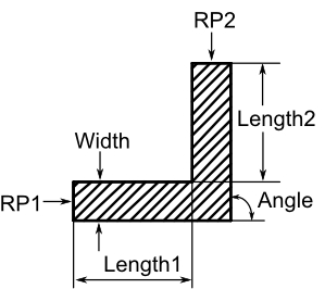
Length1 |
Length of the transmission line between port No. 1 and reference plane No. 1 (see figure below) |
|
Length2 |
Length of the transmission line between port No. 2 and reference plane No. 2 (see figure below) |
|
Angle |
Angle of the bend in degrees. The standard model allows for Angle=90, only, the 2D Enhanced EM based model allows for 0≤Angle≤90, and the 3D EM based model allows for 0≤Angle<180. |
|
Layer |
Index of the reference block layer that is used by the metallization of this block |
The properties listed above and the substrate properties of the reference block define the electrical behaviour of the block. The layout view uses another set of layout properties. These properties define the position of the block in the layout view. The electrical behaviour of the block does not depend on these properties.
This discontinuity is modelled by an equivalent circuit. The model parameters are calculated either from a formula set developed by Kirschning, Jansen and Koster, or from an expression set proposed by Garg and Bahl.
The standard, analytical model is valid either for 0.2 < Width/Height < 6.0 and 2.0 < Epsilon < 13.0 (Kirschning et al.) or for 0.1 < Width/Height < 5.0 and 2.5 < Epsilon < 15.0 (Garg, Bahl).
The reference planes are illustrated in the figure below as RP1, RP2.
See also
Block Overview, Microstrip Reference Block, Layout Properties