General User Interface
In order to open an empty CST CABLE STUDIO project, launch the CST
STUDIO SUITE from the Windows Start
menu or by clicking on the desktop icon. In the Welcome
dialog choose to create a new CST CABLE STUDIO project as shown
in the figure below:

After double-click on the CST CABLE STUDIO symbol an empty project
will be opened.
Main View
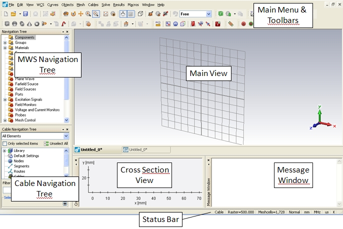
The user interface is divided into five sub-windows:
The Main View
allows the 3D visualization of the harness and its metallic surrounding
components.
The Cross Section
View allows the 2D visualization of cable cross sections.
The Cable Navigation
Tree allows the access to all objects necessary to define a complete
cable assembly in 3D. When selecting an item it will be displayed in the
Main View, Cross Section View
or in both according to the objects characteristics.
The MWS Navigation
Tree allows access to all MWS
related objects and therefore allows full access to solid modeling and
3D full wave simulation technology. When selecting an item it will be
displayed in the Main View.
The Message Window
shows general information, solver progress, warnings and errors during
project set-up simulation.
The Status Bar primarily lists
the currently selected global units and the Main
Menu allows the access to all relevant dialogs.
Interface to CST DESIGN STUDIO
Below the Main View there
are two different tabs:

Currently the CST CABLE STUDIO view  is active. Selecting the tab with symbol
 changes the view to CST DESIGN STUDIO, which grants access to the schematic
editor and the circuit simulator. The following
list gives an overview about the meaning and usage of the two different
tabs:
changes the view to CST DESIGN STUDIO, which grants access to the schematic
editor and the circuit simulator. The following
list gives an overview about the meaning and usage of the two different
tabs:
The CST CABLE STUDIO tab presents all objects and dialog boxes necessary
to define and edit cable bundles inside their 3D metallic environment.
It includes appropriate solver technology to generate equivalent circuits
which are passed to CST DESIGN STUDIO. It further enables the hybrid methods
(uni-directional cable-field coupling for radiation/irradiation or general
bi-directional field coupling) by exchanging the common mode currents
and voltages of a cable between the circuit simulator of CST DESIGN STUDIO
and the 3D field solvers from CST MICROWAVE STUDIO (see
Fundamental Methodology ).
The CST DESIGN STUDIO tab is used to define and edit loads on the equivalent
circuit of the cable harness by use of a schematic editor. It further
enables the circuit simulation of the whole system in time and frequency
domain, including a tight interface with CST CABLE
STUDIO to easily exchange impressed currents and voltages.
