Connectors and Junctions
Edit Cabling  Connectors Edit Connectors
The Edit Connectors dialog
box shows the list of all available connectors. The dialog box can be
also accessed via Cable Navigation
Tree: Connectors:
selecting the Connectors folder
and either double-clicking or choosing Edit inside the context menu
(via right-mouse-click). The icons on the top of the dialog box
enable actions which are explained below. The meaning of each icon is
also explained by tool-tips. To see a tool-tip just move the mouse-pointer
over the corresponding icon:
 Create a new connector
 Duplicate a connector
 Delete the selected connector
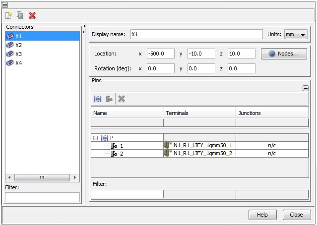
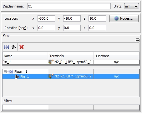
Every Connector requires a unique name that has to be assigned in the
field Display name. The underlying
unit size for geometry definition can be selected with the Units
pull-down menu. Changing the unit does not affect the size but just displays
the original size in the new unit. The position can be either defined
directly inside the Location field
or by selecting an available Node
with the help of the Nodes button.
The orientation of the connector in the 3D space can be defined in the
Rotation field. In the 3D
Main View connectors are displayed by yellow boxes.
Connecting connector pins with signal terminals
The connection of connector pins
with existing signal terminals
of a cable has to be done inside the Pins-frame.
Connector pins are grouped hierarchically into sub-connectors, the so-called
Plugins. All plugins and their
corresponding pins are listed in a table. To enable the three icons on
top of the table the predefined default Plugin_1
has to be selected as shown in the figure below:
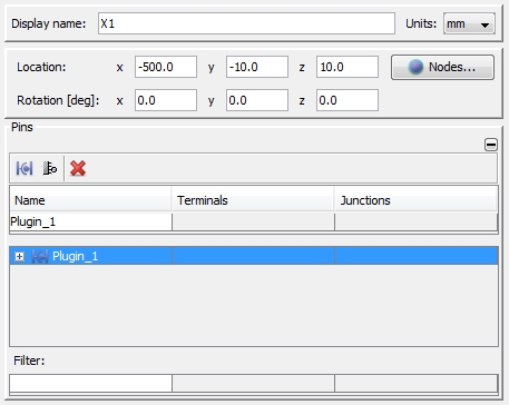
The three icons enable the following actions:
 Create a
new plugin: generates a new sub-connector
Create a
new plugin: generates a new sub-connector
 Create a
new pin: generates a new pin inside the selected plugin
Create a
new pin: generates a new pin inside the selected plugin
Delete: deletes
the selected plugin or pin from the table
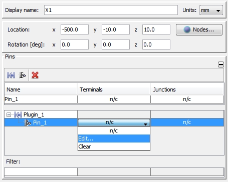
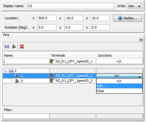
In order to connect a connector pin to an existing signal terminal,
the pin has to be selected first. Next, the corresponding cell inside
the Terminals column has to be
selected. A pull-down menu will appear as shown in the figure below:
After pressing Edit the
Edit Terminals dialog box will
appear listing all available signal terminals. The signal terminals are
grouped into so called Interfaces
according to the Nodes they belong to. In order to assign Pin_1
to a signal terminal at node N2,
Interface-N2
has to be expanded as shown in the figure below:
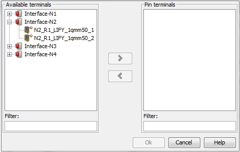
In order to complete the assignment, a certain signal terminal inside
the Available terminals frame
has to be selected and moved to the Pin
terminal frame on the right side by using the arrow button ">". As a result the signal terminal
will be removed from the list on the left side. After pressing the OK button the signal terminal is linked
to the connector pin as shown in the figure below:
Note:
It is possible to link more than one signal terminal
to a connector pin. All terminals, that are moved from the Available
Terminals list on the left side (of the Edit
Terminals dialog box) to the Pin
Terminal list on the right side, are automatically linked together
and attached to the corresponding connector pin. Connector pins which
connect different signal terminals will not appear in the schematic block
later on.
Junctions
In a similar way as connector pins are connected to signal terminals,
connector pins can be connected to other connector pins as well. This
is possible by means of Junctions.
A junction between two connector pins can only be made inside the Edit Connector dialog box. In order
to connect two pins from the same or different connectors, the user has
to select the first pin and click on the corresponding cell in the Junctions column as shown in the figure
below:
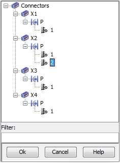
After selecting Edit the
Define Junction dialog box will
appear listing all available connector pins (according to the Connectors
they belong to). In order to connect both pins of connector XN5,
the second pin P_2
has to be selected as shown in the figure below:
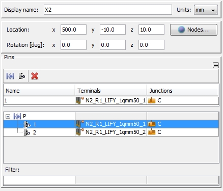
After pressing the Ok button
a Junction will be generated as shown in the figure below. The name C is chosen by the program. and can
be changed.
NOTE:
Junctions can be made between pins from different
connectors as well. But the user has to keep in mind that Junctions are
treated as ideal connections in the later circuit simulation. Therefore,
it does only make sense to connect pins which are close to each other
(compared to the smallest wavelength which is significant in the later
circuit simulation).
Edit Cabling Junctions
The Edit Junction
dialog box can be also accessed via the Cable Navigation Tree:
Junctions.
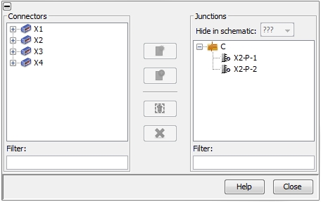
On the right side all available Junctions
are listed. The name of
a Junction can be edited by right mouse clicking on it and choosing Rename from the pull-down menu. In addition,
it can be specified whether the connected pins of a Junction should still
be displayed on the schematic block or not - the default is to Hide
in schematic. There is the possibility to add further pins to the
Junction (or remove some of them). This can be done by using the Connectors frame on the left side and
the Add symbol in the middle
of the dialog box. The Connectors
frame lists all available connectors with their corresponding plugins.
As soon as an additional connector pin is selected, the
Add button in the middle will
be activated. Pressing this button moves the selected pin to the right
side and the existing Junction will be extended.
In the following list the icons in the middle of the dialog box will
be explained. The meaning of each icon is also explained by tool-tips.
To see a tool-tip just move the mouse-pointer over the corresponding icon:
New: selecting
two Connector pins from the left
side and pressing this buttons generates a new
Junction on the right side
 Add a selected
Connector pin from the left side
to the selected Junction on the
right side
Add a selected
Connector pin from the left side
to the selected Junction on the
right side
 Remove a
selected Junction pin (on the
right side)
Remove a
selected Junction pin (on the
right side)
Delete a selected
Junction (on the right side)
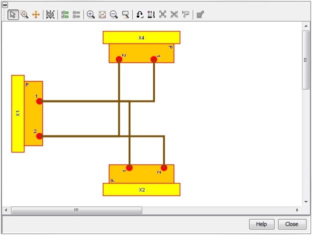
Show in Schematic
In complex setups it can be useful to visualize which connector pins
are connected by signal paths (which means by
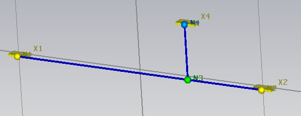
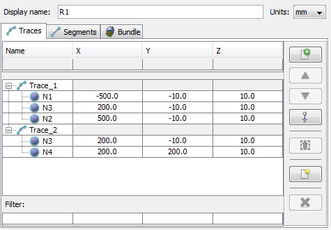
any kind of cable). The figure below shows a Route with a stub trace.
Two single wires are assigned to the route and on each end-node (N1, N2,
N4) connectors are connected
to the wire terminals.
In order to see how the different connector pins are connected between
each other, the user has to go into Cable
Navigation Tree: Connectors,
selecting a connector as a starting point by right mouse click and choosing
Show in Schematic from the pull-down
menu. A separate window will appear displaying the connections from the
Start-Connector to all other connectors which are connected to the Start-Connector:
The window enables to emphasize connections by simply selecting them
by a left mouse click. The style on how the connectors and the connections
shall be visualized can be changed by using the View
Options dialog box. The dialog box can be called
either by right mouse clicking inside the window and
choosing View Options
or by pressing the  icon at the top of the window.
The meaning of every icon inside the top tool bar is
explained by tool-tips. To see a tool-tip just move the mouse-pointer
over the corresponding icon.
