
 Create a new coaxial cable
 Duplicate a selected coaxial cable
 Import cables from an external Cable
Library File (not restricted to coaxial cables)
Import cables from an external Cable
Library File (not restricted to coaxial cables) Export cables into an external Cable
Library File (not restricted to coaxial cables)
Export cables into an external Cable
Library File (not restricted to coaxial cables) Remove all coaxial cables which are not used within
the current project
Remove all coaxial cables which are not used within
the current project Delete the selected coaxial cables.
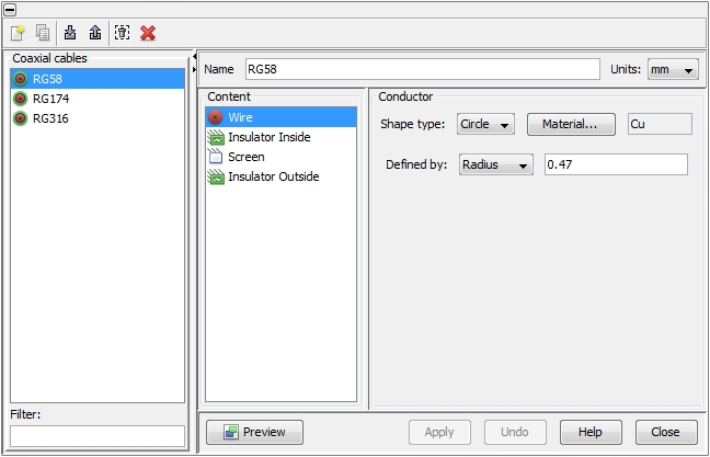
The definitions for both objects are similar to the Wire definition dialog.
Simplified model:
Defines the transfer impedance with a Transfer-resistance and a Transfer-inductance.
Kley's mode (see References):
Defines the transfer impedance by four design characteristics of the braid:
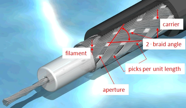
Filament diameter: the diameter of the individual metallic wires a braid is composed of. Another expression for filaments is "ends" (see figure below).
Number of filaments in one carrier: number of individual wires (ends) which are grouped to a carrier (see figure below).
Number of carriers: number of carriers, usually 16 for the most telecommunication braided cables (see figure below).
The product of the three parameters from above specifies a length. This length is not allowed to exceed the double of the screen's circumference, which is implicitly defined by the Insulator inside setting (see figure of dialog box above). The fourth characteristic specifies the weaving style and can be expressed by one of the following three parameters:
either Braid angle: the angle formed by the carriers with the longitudinal axis of the cable (see figure below).
or Optical Coverage: the percentage of screen surface which is filled by metallic wires to the overall surface of the screen (= metal wires + apertures, see figure below)
or Picks per unit length: the number of carrier crossing points per longitudinal unit length (see figure below).
The relationship between the three parameters can be expressed in algebraic formulas. With:
D: diameter under the braid (defined by the isolator below)
d: diameter of a single filament
N: number of filaments in each carrier
C: number of carriers
F: fill factor
a: braid angle
P: picks per unit length
O: optical coverage
F = N . P . d / sin a;
O = 2 . F - F2;
tan a = 2 p . (D+2d) . P/C;
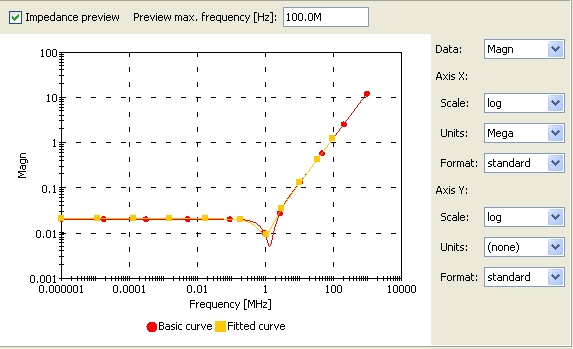
Measured results:
The Edit Measurements... button enables the import of an ASCII file which contains a list of frequency points and corresponding complex (or real) impedance values (in a comma separated form). In order to filter noise out of the measured data two parameters are available: The field Neighbors considered for smoothing specifies how many neighbors in front and behind a certain frequency point shall be used for filtering. The field Repetitions specifies the number of filter runs that should be performed. If the number is set to zero no filtering will be performed.
"Shielding Effectiveness of Braided-Wire Shields", E.F. Vance, IEEE Transactions on EMC, Vol. 17, No. 2, May 1975
"An Improved Model for the Transfer Impedance Calculation of Braided Coaxial Cables", S.Sali, IEEE Transactions on EMC, Vol. 33, No. 2, May 1991
"Optimized Single-Braided Cable Shields", T. Kley, IEEE Transactions on EMC, Vor. 35, No. 1, February 1993
"EMC Analysis Methods and Computational Models", F.M. Tesche, M.V. Ianoz, T. Karlsson, John Wiley & Sons, 1997
NOTE:
Screening conductors are treated like any other conductor. They carry signals and have got terminals at either side regardless if they are solid or braided shields.